Home Automation Ethernet eHouse version .
Connectors of Ethernet controllers
Description refers to average Ethernet controllers:
- EthernetRoomManager
- EthernetHeatManager
- EthernetSolarManager
- Other dedicated Ethernet controllers based on the same PCB
Description is NOT for big controllers
- CommManager
- LevelManager
Most eHouse controllers connectors are double row IDC with different amounts of pins, for easy installation and quick connection, and to provide for easy installation through the use of tape-mounted flat with clenched IDC connectors on the ends (special crimper connector ID) .
Assembly and disassembly wiring does not require forging grooves in the walls due to the thickness of the strip is about 1mm flat .
Totally do not need a screwdriver to connect the wires to the large number of contacts and the controller clamping flat cable regardless of the number of cores it takes several seconds.
This facilitates the removal, service and diagnostics for the detection of problems in the case of wrong installation.
Ethernet 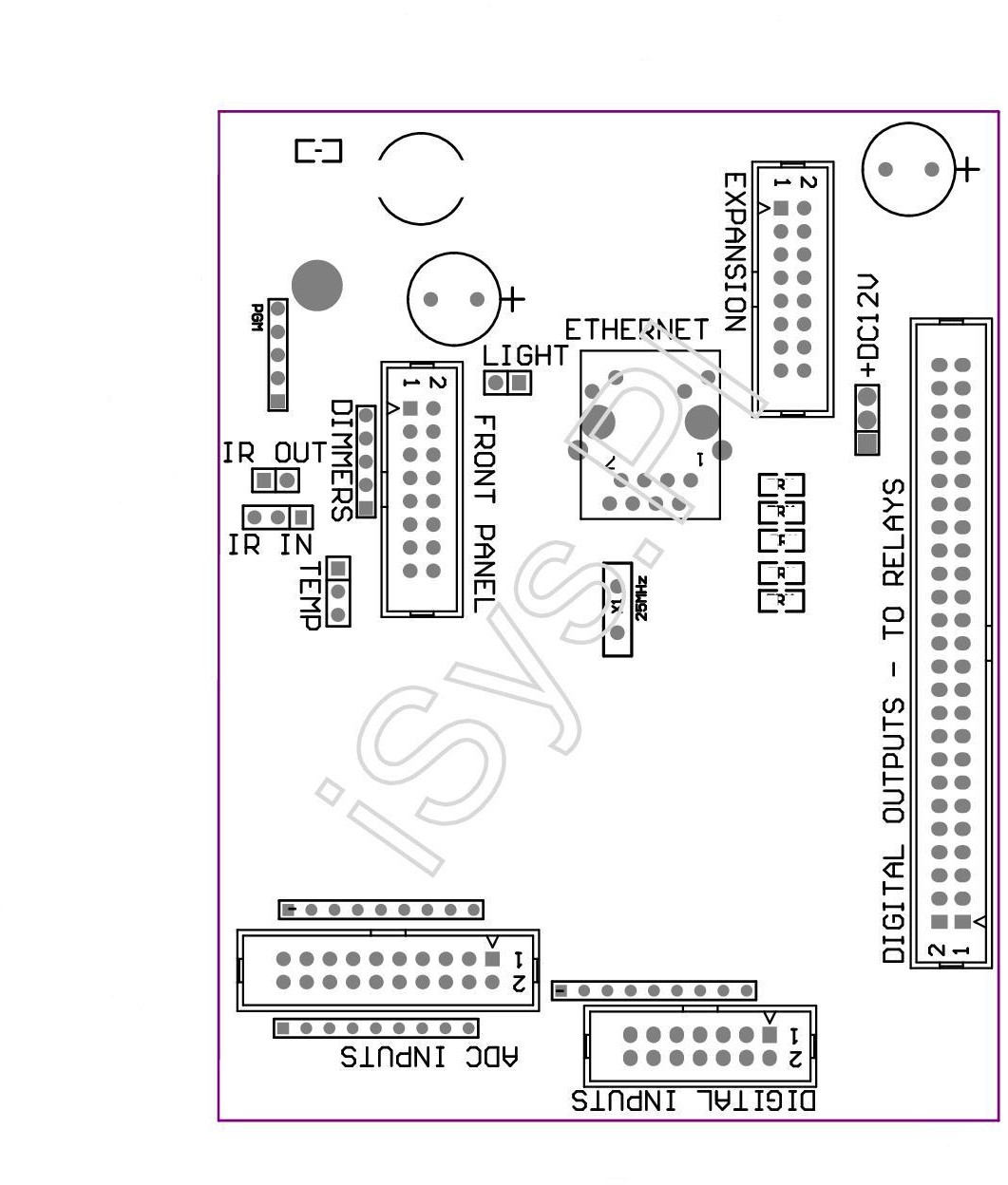
Leads Intelligent Ethernet controllers home eHouse EthernetRoomManager , EthernetHeatManager , EthernetSolarManager
Pin No. 1. field is marked with a square solder pad on the PCB and the housing additionally arrow slot. After the first pin is located in the middle of the housing cut-out slot , prevent reverse insertion of the plug.
Pins are numbered in sequence with priority columns:
____________________________________________________________
| 2 4 6 8 10 12 14 16 18 20 22 24 26 28 30 32 34 36 38 40 42 44 46 48 50
| 1 3 5 7 9 11 13 15 17 19 21 23 25 27 29 31 33 35 37 39 41 43 45 47 49
| ^ ___________________ ____________________________________
ADC INPUTS – Analog Inputs – Digital Measurement (ADC INPUTS) (0 ; 3V3) Relative Weights – Do not connect any external voltage (IDC-20)
1 – Gnd / Ground (0V)
2 – Gnd / Ground (0V)
3 – ADC IN 2
4 – ADC IN 10
5 – ADC IN 3
6 – ADC IN 11/12 * DIGITAL INPUT
7 – ADC IN 4
8 – ADC IN 12/11 * DIGITAL INPUT
9 – ADC IN 5
10 – ADC IN 13/10 * DIGITAL INPUT
11 – ADC IN 6
12 – ADC IN 14/9 * DIGITAL INPUT
13 – ADC IN 7
14 – ADC IN 15 / DIGITAL INPUT 8 *
15 – ADC IN 8 (optional temperature sensor mounted on the module or external panel ERM)
16 – ADC IN 0
17 – ADC IN 9 (optionally mounted light sensor (phototransistor +) on the module or external panel ERM)
18 – ADC IN 1
19 – VDD (+3V3) – Requires a jumper to power the ERM limiting current / temperature sensors for power (resistor 100 OM)
20 – VDD (+3V3) – Requires a jumper to power the ERM limiting current / temperature sensors for power (resistor 100 OM)
* shorten with digital inputs – do not connect
DIGITAL INPUTS – Digital Input (On/Off) short to ground or open (do not connect any external voltage) (IDC-14)
1 – Gnd/Ground (0V)
2 – Gnd/Ground (0V)
3 – Digital Input 1
4 – Digital Input 2
5 – Digital Input 3
6 – Digital Input 4
7 – Digital Input 5
8 – Digital Input 6
9 – Digital Input 7
10 – Digital Input 8 *
11 – Digital Input 9 *
12 – Digital Input 10 *
13 – Digital Input 11 *
14 – Digital Input 12 *
* shorten to Analog Inputs
DIGITAL OUTPUTS – With controllers digital outputs for direct connection to the relay coil control relay (IDC-40 or IDC-50)
1 – VCCDRV – Protection against Surge for the relay connected to the relay coil 12V (diodes to VCC & GND)
2 – VCCDRV – Protection against Surge for the relay connected to the relay coil 12V (diodes to VCC & GND)
3 – Digital output for direct connection to the relay coil (12V/20mA) No.1
4 – Digital output for direct connection to the relay coil (12V/20mA) No.2
5 – Digital output for direct connection to the relay coil (12V/20mA) No.3
6 – Digital output for direct connection to the relay coil (12V/20mA) No.4
7 – Digital output for direct connection to the relay coil (12V/20mA) No.5
8 – Digital output for direct connection to the relay coil (12V/20mA) No.6
9 – Digital output for direct connection to the relay coil (12V/20mA) No.7
10 – Digital output for direct connection to the relay coil (12V/20mA) No.8
11 – Digital output for direct connection to the relay coil (12V/20mA) No.9
12 – Digital output for direct connection to the relay coil (12V/20mA) No.10
13 – Digital output for direct connection to the relay coil (12V/20mA) No.11
14 – Digital output for direct connection to the relay coil (12V/20mA) No.12
15 – Digital output for direct connection to the relay coil (12V/20mA) No.13
16 – Digital output for direct connection to the relay coil (12V/20mA) No.14
17 – Digital output for direct connection to the relay coil (12V/20mA) No.15
18 – Digital output for direct connection to the relay coil (12V/20mA) No.16
19 – Digital output for direct connection to the relay coil (12V/20mA) No.17
20 – Digital output for direct connection to the relay coil (12V/20mA) No.18
21 – Digital output for direct connection to the relay coil (12V/20mA) No.19
22 – Digital output for direct connection to the relay coil (12V/20mA) No.20
23 – Digital output for direct connection to the relay coil (12V/20mA) No.21
24 – Digital output for direct connection to the relay coil (12V/20mA) No.22
25 – Digital output for direct connection to the relay coil (12V/20mA) No.23
26 – Digital output for direct connection to the relay coil (12V/20mA) No.24
27 – Digital output for direct connection to the relay coil (12V/20mA) No.25
28 – Digital output for direct connection to the relay coil (12V/20mA) No.26
29 – Digital output for direct connection to the relay coil (12V/20mA) No.27
30 – Digital output for direct connection to the relay coil (12V/20mA) No.28
31 – Digital output for direct connection to the relay coil (12V/20mA) No.29
32 – Digital output for direct connection to the relay coil (12V/20mA) No.30
33 – Digital output for direct connection to the relay coil (12V/20mA) No.31
34 – Digital output for direct connection to the relay coil (12V/20mA) No.32
35 – Digital output for direct connection to the relay coil (12V/20mA) No.33
36 – Digital output for direct connection to the relay coil (12V/20mA) No.34
37 – Digital output for direct connection to the relay coil (12V/20mA) No.35
38 – GND/Ground 0V (Alternatively, to power connector 3 pin ONLY if cable length of less than 40cm flat)
39 – GND/Ground 0V (Alternatively, to power connector 3 pin ONLY if cable length of less than 40cm flat)
40 – GND/Ground 0V (Alternatively, to power connector 3 pin ONLY if cable length of less than 40cm flat)
41 – GND/Ground 0V (Alternatively, to power connector 3 pin ONLY if cable length of less than 40cm flat)
42 – GND/Ground 0V (Alternatively, to power connector 3 pin ONLY if cable length of less than 40cm flat)
43 – GND/Ground 0V (Alternatively, to power connector 3 pin ONLY if cable length of less than 40cm flat)
44 – GND/Ground 0V (Alternatively, to power connector 3 pin ONLY if cable length of less than 40cm flat)
45 – GND/Ground 0V (Alternatively, to power connector 3 pin ONLY if cable length of less than 40cm flat)
46 – GND/Ground 0V (Alternatively, to power connector 3 pin ONLY if cable length of less than 40cm flat)
47 – GND/Ground 0V (Alternatively, to power connector 3 pin ONLY if cable length of less than 40cm flat)
48 – GND/Ground 0V (Alternatively, to power connector 3 pin ONLY if cable length of less than 40cm flat)
49 +12V power input ERM (alternatively with 3 pin power connector for flat cable length of less than 50cm)
50 +12V power input ERM (alternatively with 3 pin power connector for flat cable length of less than 50cm)
POWER DC +12 V (3 – Pin connector)
1 – GND/Ground/0V
2 – GND/Ground/0V
3 – Power supply 12V/0A5 (Power controller) UPS (optional)
FRONT PANEL – External expansion connector panel (IDC-16) – only to connect eHouse system components
1 – +12VDC power supply (input / output max 100mA) *
2 – +12VDC power supply (input / output max 100mA) *
3 – Digital output number 34 (controller output)
4 – VCC 3V3 (internal stabilizer output)
5 – IR IN (input from an external IR receiver)
6 – ADC IN 8 (optional temperature sensor mounted on the module or panel outside ERM)
7 – TX1 (RS232 TTL Transmit) or other functions for the external panel (Do not connect external devices)
8 – RX1 (RS232 TTL Reception) or other functions for the external panel (Do not connect external devices)
9 – ADC IN 9 (optionally mounted light sensor (phototransistor +) on the ERM module or an external panel)
10 – PWM 1 (PWM dimmer output 1 or TTL red – without power controller) 3V3/10mA (to control LED controller optocoupler transmit power)
11 – PWM 2 (dimmer PWM output 2 or TTL green – without power controller) 3V3/10mA (to control LED controller optocoupler transmit power)
12 – PWM 3 (Output PWM dimming 3 or TTL blue – without power controller) 3V3/10mA (to control LED controller optocoupler transmit power)
13 – IR OUT – Infrared signal output (for connecting and transmitting IR LED current limiting resistor 12V/100mA)
14 – RESET – Reset controller (short to ground)
15 – GND/Ground/0V *
16 – GND/Ground/0V *
* Power EthernetRoomManager from the external panel (disconnect other power supply (+12VDC) to provide a good common ground especially with Ethernet Router
ETHERNET-RJ45 connector to connect to a LAN (10Mbs)
This is a standard Ethernet jack RJ45 connector requiring clamped on the cable UTP-8.
LIGHT – sensor (2 pin) – optional light sensor mounted alternatively an external panel
1 – GND/Ground/0V
2 PHOTOTRANSISTOR + (or other light-sensitive element Photodiode , photoresistor) ADC IN 9 (optional light sensor mounted on the module or panel outside ERM)
TEMP – Temperature Sensor (3 pin) – optional temperature sensor mounted alternatively an external panel (MCP9701 , MCP9700)
1 – 3V3 power supply temperature sensor
2 – ADC IN 8 (optional temperature sensor mounted on the module or panel outside ERM)
3 – GND/Ground/0V
Dimmers – Output PWM dimmers (5 pin) to control optoizolators (3V3/10mA)
1 – PWM 1 (PWM dimmer output (TTL ) 1 or red – without power driver) 3V3/10mA (to control LED optocoupler of power driver – Anode)
2 – PWM 2 (PWM dimmer output (TTL ) 2 or green – without power driver) 3V3/10mA (to control LED optocoupler of power driver – Anode)
3 – PWM 3 (PWM dimmer output (TTL ) 3 or blue – without power driver) 3V3/10mA (to drive of LED optocoupler of power driver – Anode)
4 – GND / Ground / 0V – Optocoupler LED cathode for PWM power drivers *
(5;+12) VDC power supply (input / output max 100mA) *
* Power EthernetRoomManager from dimmers Power driver (disconnect other power supply (+12VDC) to provide a good common ground especially with Ethernet Router
Do not connect external devices , interfaces variants for eHouse controllers.
Connecting to other signals may damage the controller.
These pins are shorted to pins Digital Inputs, Analog , digital outputs directly on the processor without any security.
Ethernet eHouse – Home Automation – Room Controller