Home_Automation eHouse is an advanced solution for electronic home, having implemented many algorithms , which operate independently of each other.
Testing and Debugging controller behavior is much easier on a table than installed in the building .
Demonstration / Evaluation Module should therefore be the first tool, that allows you to design and test the installation and configuration of home automation, yet at the stage of design automation control .
Smart home demonstration module of eHouse4Ethernet allows you to test controllers, on the table without the need for much more time-consuming installation at home.
Application of evaluation module allows you to overturn myths and assumptions about the real controllers in the system close to the target environment .
Evaluation Module allows testing of all Ethernet controllers :
- CommManager
- LevelManager
- EthernetRoomManager
- EthernetHeatManager
- other large-scale Ethernet-based controllers on the PCB of CommManager / LevelManager
- other medium based Ethernet controllers on the PCB of EthernetRoomManager
Allows direct connection of all input and output signals to the module:
- connected display for output status LEDs
- connected analog sensors
- lighting – phototransistor for visible light
- temperature – LM335 , MCP9700 , MCP9701
- switches connected to the digital inputs
- connected LEDs for display dimmer level
- IR receiver to control EthernetRoomManager
- IR emitter to control external audio – Video systems
In addition, the demo unit has connectors for automatic testing of all Ethernet controllers , performance and hardware resources:
- digital inputs
- digital outputs
- measuring inputs – Analog/Digital converters
- PWM dimmers
- IR transmitter
- IR receiver
In case of doubt as to whether the controller is ok ,it is possible to self-test software to test the module for any damage .
In one part of the evaluation of the module , allows to determine if any problems are caused by the automatic
- damage control
- bad module configuration
- error or system failure
- damage to the switch , Sensor , Dimmer , actuator
Demonstration and evaluation of the outputs on module : 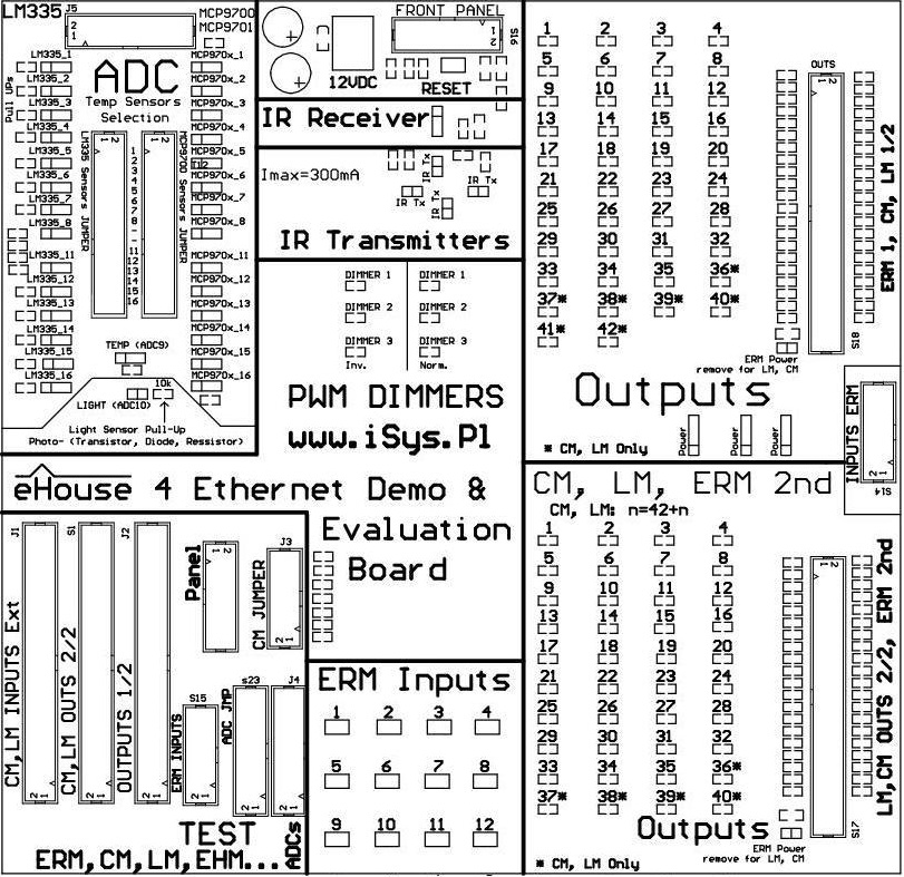
Demonstration module has several sections to test control algorithms , functionality and configuration:
- Sections 2 output “Outputs” allowing simultaneous testing of two medium-sized controllers or one large
- “ADC” – sensors to evaluate all analog / digital converter inputs
- “Inputs” – digital inputs
- “IR Transmitter” – IR transmitter
- “IR Receiver” – IR receiver
- “Dimmers” – PWM Dimming normal and reversed
- “TEST” – controller self-test section
Digital input section – OUTPUTS
It has installed LEDs connected to each digital output of any controller .
Activation of the output will illuminate LED connected to a specific output of controller .
Sections hove respectively 42 and 40 outputs allow testing of all types of Ethernet controllers.
Digital Input Section – INPUTS
It has a installed switches “push button” connected to each input (max 12) , shorting them to ground when the button is pressed.
Connector inputs are compatible with standard ERM.
Section dimmers – Dimmers
Each controller has 3 DC PWM dimmers without power driver.
The output can directly control the LED of power driver transmitting insulator in two ways:
- Normal – LED dimmer placed between the output (anode) and the ground of the system (cathode)
- Inverted (INV) – placed between the output of the LED dimmer (cathode) and the positive voltage controller 3V3 (anode)
In the dimmer uses LEDs for illumination level .
Sections IR transmitter and receiver – IR
- Infrared receiver section includes an infrared signal receiver IC for the self-test or control ERM with standard infrared remote control Sony
- IR transmitter section includes infrared emitters (LEDs emitting in the infrared) with current limiting resistors to a safe value for the controller and LEDs . It is used to test the transmission of control signals for audio-Video equipment from the ERM controller
Analog/Digital Converter Section – ADC
The section contains a set of sensors that can switch analog inputs for sensors:
- up to 15 MCP9700 or MCP9700 sensor
- up to 14 sensors LM335 with the necessary resistors to supply voltage (3V3) of controller (Pull Up)
- light sensor – phototransistor
It also contains a set of “jumpers” to choose to connect to any analog sensor inputs for sensors available LM335 and MCP970x .
Auto-test controllers Section – TEST
This section includes all connectors properly connected (inputs , Outputs) of Ethernet controllers , to automatically check for controller testing software loaded .
This will allow for a reliable check all the hardware you run the test events and displaying errors .
It is used both for the automatic diagnosis of the controllers of large (based on the CM , LM) and average (based on the ERM , EHM) .
For more information about Ethernet controllers: Ethernet eHouse Home Automation – RoomManager
Ethernet eHouse Home Automation – Apartment Controller
Ethernet eHouse Home Automation – Security System Rollers , Gates , gateways – controller