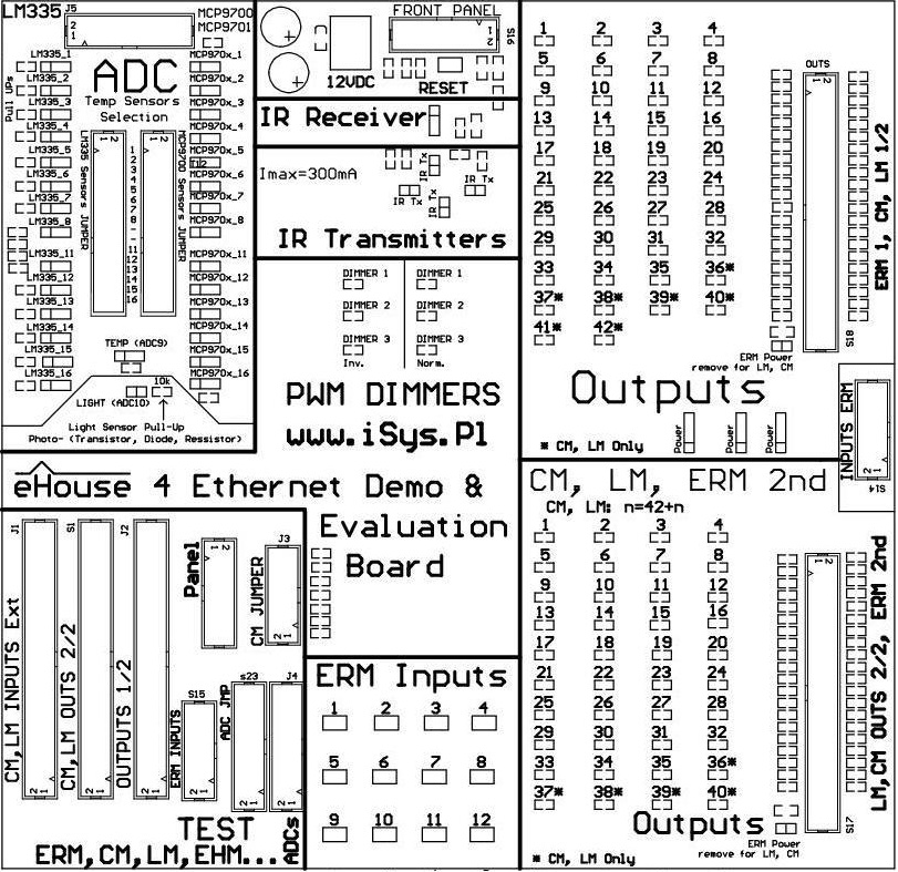
Ethernet eHouse – Smart home demonstration module, allows testing and evaluation of all the controllers of eHouse Home Automation.
Evaluation Module of eHouseEthernet building automation system contains all hardware resources (LEDs, Switches, Sensors) stored on the PCB replacing production installation at home.
Connection demonstration module to the controller is very simple and only requires connection of relevant “tapes” between the microprocessor controller and the demo PCB.
Ethernet Controllers can be divided into two main variants of the hardware:
- average controllers – based on EthernetRoomManager (ERM) PCB
- large controllers – based on CommManager/LevelManager (CM, LM) PCB
In this post we will discuss testing and evaluation of large controllers (based on ERM) module using Ehouse4Ethernet DEMO.
First, make sure that the power module is disconnected from demo and ERM has unconnected all the cables and connectors .
To fully analyze the behavior of the controller, you should connect the following LM/CM connectors between modules DEMO and LM/CM:
- Remove all the wires from the connectors in the “TEST” section
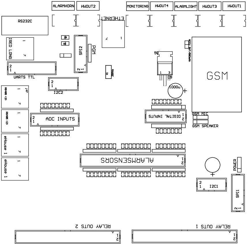
- 50 pin flat tape “outputs” (S18) connector “Relay Outs 1” . And remove the jumper “ERM Power” near the connection s18
- 50 pin flat tape “outputs” (S17) connector “Relay Outs 2” . And remove the jumper “ERM Power” near the connection s17
- 20 pin flat table (J5) for Analog/Digital converters – Measurement.
- Connect The power cord – connector “Power” between CM/LM and the module demo
The next step is an appropriate combination of sensors connected to the inputs of the ADC .
CM doesn’t support ADC completly and measurement results are not acurate due to GSM module.
Remove the jumper “Light”, connecting light sensor to the ADC.
The next step is to configure remaining temperature sensors, connecting them to the required inputs.
Look for the 2x32pin, allowing the individual connecting of sensors LM335 or MCP970x to any input of controller.
You can select only one type of sensor for input.
Activation of the sensor also provides connection LM335 “Pull Up” resistor to 3V3 which provides power to the sensor.
This is a much more secure connection of the sensor than powered sensor circuit, as the sensor pins are not touching power and there is not risk to overcurrent power supply.
LM335 Sensors for Ethernet controllers do not have the full-scale measurement and can measure temperatures up to about 56 degrees C.
In the case of very low temperatures may also have the effect of self-heating by the because it works with larger current, because these sensors are working optimally for 5V supply voltages.
For example, To connect the sensor to the input of LM335 No.7, in the 32-pin connectors remove the jumper in row 7 for MCP970x and short-circuit for LM335.
To connect the sensor to the input MCP970x No. 6 to the 32-pin connectors remove the jumper in row 7 for LM335 and close to MCP970x .
Be aware that, depending on the type of controller (hardware and interconnection module) part of the inputs can be connected on a printed circuit board of the controller to internal resources.
Please refer to the detailed documentation of the controller , measuring sensors that are not physically connected to other resources.
The next step is to connect the Ethernet (LAN) router or Switch to the eHouseEthernet controller RJ-45.
After checking and verifying that all cables are correctly connected and tightened 12VDC power supply can be connected to the module demo board which is also the power of the controller.
Digital Out Expanded Testing
States of the digital outputs are displayed on the LEDs located in sections “OUTPUTS” of evaluation module.
LED lights for the corresponding output is equivalent to the turn on of a relay in production system.
Demonstration unit has two independent “OUTPUTS”, sections which allows simultaneous checking all outputs of large controllers (CM , LM , etc) .
“ERM Power” in each section of “OUTPUTS” MUST BE REMOVED as the Large Ethernet controllers are not derived high voltage on these way.
Power Connection in this way can cause major damage to the controller.
They must be fed a normal power cable as standard power connector controllers.
Testing of Digital Inputs
The digital inputs of Ethernet controllers are connected via “Pull Up” resistors to the controller power supply (3V3) voltage.
It is necessary to activate the input by short to ground control (for LM) and disconnect from ground for (CM).
Because of control events can come from a variety of sources , mono-stable switches are used (bell) to not collide with other signals and events issued.
This prevents the performance of collision events when such switch forces such as the inclusion of an external panel on the output we get the event off the same output .
Inputs (12) are connected directly to the Ethernet module switches DEMO ( “micro swich” ) Is listed in “ERM Inputs” .
Switches installed on the demo unit is “normally open” NO that is compliant with ERM , LM and not CommManager .
Event will be issued on disconnection the terminals from the ground (for LevelManager) .
To use the switches on the module connected to CommManager demo or LevelManager need to make an adapter connector (IDC14 to IDC50).
In addition, we have available only 12 inputs .
Alternatively, you can test un-isolating input 50pin flat cable ends, and directly shorting or separating wires to the ground.
In this case it is also necessary CommManager inversion of input into CommManagerCfg.exe configuration application , setting the flag “Invert” switches to use the module DEMO . This force opposite behavior of the switch.
The next step is to link system events associated with a digital input for the LM/CM.
This is done in the CommManagerCfg.exe application, by selecting an event from the list of events for a controller.
In the case of single input in select control event “Toggle” for Output would result in, each time you press the switch to change the state of the associated output.
You can also control a single output instead run programs. The program integrates any combination of the outputs of the digital outputs (on, off or leave unchanged) for LM.
This will allow you to control complex light scenes consisting of a few/several independent lighting circuits with a few switches. After configuring the digital inputs, press “Save Settings” on the main form to load the configuration to the controller .
After configuring the digital inputs, press “Save Settings” on the main form to load the application to the controller.
Testing measurement from sensors
After connecting and configuring the analog/digital converter input on demo module, what was discussed at the beginning of the post, propper sensor type must be set in the application configuration CommManagerCfg.exe for ADC input in for sensor.
Otherwise, the sensor value will be calculated in the wrong way by control panels software, and set invalid thresholds (eg . temperature) for running events will not make sense .
To change the type of sensor you must select “Advanced Settings” .
To test exceeds the thresholds (min, max) for a given input A/D converter, it is necessary to link the relevant event for (min , max) in the application CommManagerCfg.Exe.
Normally it turn on/off one of the outputs (to which in the production system device is connected to adjust a given physical level such as : heater, radiator valve, valve for floor heating in the room, etc. .)
In the case of heatting threshold (min) turn on and its stop in case of the threshold (max) turn off heater. This will allow you to achieve automatic control of the physical value (eg. temperature) and keeping it in the range (min, max).
It should also be noted, the setting of thresholds for all measuring inputs are grouped in A/D programs “ADC Settings” programs that integrate automated control of heating control, lighting, humidity, etc .
Taken into account are the thresholds for the currently running program.
When you enter configuration settings , measurement thresholds , ADC programs and loaded into the controller , so you should also run a configured A/D program.
For more information: Home Automation – eHouse 4 Ethernet – Control room EthernetRoomManager . Lighting Control , heating , HiFi equipment
Home Automation – eHouse 4 Ethernet , Controller – blinds , gates , marquess , alarm SMS alarm notification – The controller drives .
Home Automation eHouse 4 Ethernet , Controller – floor , home , Apartment Lighting and heating control centralized version .
Home Automation – eHouse 4 Ethernet – Technical Documentation